
This cabling is a one-time fixed installation with all the cables made exactly to length and neatly placed in cable-guides/trays in the rack. That is 30x8= 240 ports which fits in 5x 48 port patch-panels. Top 6U is for patch-panels: Also ports at the front.įrom the back of the patch-panels we just run 8 UTP cables (CAT7) to the back of each of the 30 U's. On the side of each rack is filler plate, except at the U's with switches so there is some cold airflow to the side-intakes on the switches. Next 6U is for switches: ports at the front. (Not higher, to difficult to mount/unmount them.) For each 42U rack we reserve the lower 30U for servers.

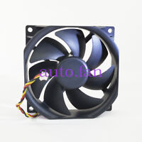
Precisely because of these issues nowadays we do it completely different in our bigger server-rooms. Be prepared to leave 1 U above and below a switch unused, just to give yourself some working room. It might be OK if you only need to (re-)patch them on very rare occasions. This makes cabling awkward because you will have to reach quite a long way into the rack to reach the RJ45's. Then you could mount them, ports facing backwards, in the front of the rack. In most switches that I took apart the fans plug directly into a motherboard connector and are not reversible. I have no idea if this is electrically feasible and how the firmware would react on a 2960. When you mount on the front you will have to run most server-cabling from the back to the front (if your servers have most wiring on the back) which makes for messy cabling. Unfortunately this is usually not the case in a strict hot/cold isle setup. That will only be OK if you have cold airflow running on the side of the rack so the switch can get sufficient cooling. If you mount them unmodified backside of the rack just about the entire switch is in the hot zone.

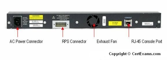
Cisco 2960 switches pull in cool air from the sides and exhaust to the rear.ĭepth-wise they are 1/3 to 1/2 rack-depth (depending on exact model switch and rack).


 0 kommentar(er)
